Installing the Service Station
The Service Station fits in the slot immediately above the Ink Tank slots.
Procedure:
| 1. Make sure the printer is powered OFF. If the printer is not powered off, press the ON/OFF button once and wait about 45 seconds for the print engine to power off (all control panel light’s off). Then turn the Main Power Switch OFF. | ||
| 2. Open the Top Cover. | ||
| 3. Open the Ink Tank Door (hinged at bottom) to expose the “Service Station Slot”. Tip: On older units you will need to remove the Exit Roller Cover by removing the four (4) screws. This is not necessary on newer units. |
||
| 4. If you are installing a New Service Station; carefully remove the Service Station from its packaging. NOTE: Loose parts may fall out. Keep wiper roller side facing up, when removing the packaging. | ||
| 5. If you are installing a New Service Station; carefully remove the Service Station from its packaging. NOTE: Loose parts may fall out. Keep wiper roller side facing up, when removing the packaging. |
|
|
| 6. Slide the Cable Securing Latch open on the Service Station Circuit Board; as shown | ||
| 7. Locate the Ribbon Cable (from within the Service Station Slot). Insert the Ribbon Cable (blue side up) into the space under the Cable Securing Latch [1]. Make sure the ribbon cable is pushed in all the way and is NOT crooked. Then close the Cable Securing Latch [2]. | ||
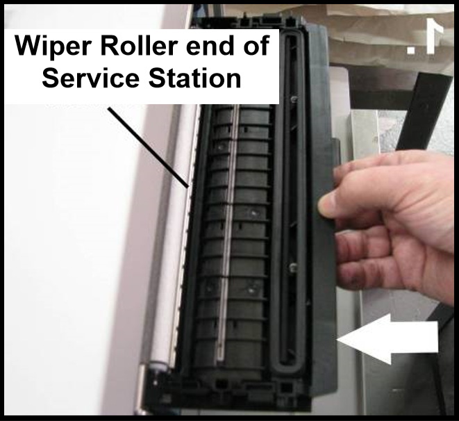
| 8. Once the Ribbon Cable is properly connected to the Service Station Circuit Board; gently slide the Service Station, wiper roller end first, into the Service Station Slot until it stops. The Service Station fits into the slot immediately above the Ink Tank slots. NOTE: The Ink Tank Door must be open to perform this procedure. |
||
| 9. Carefully Open the Clamshell. | ||
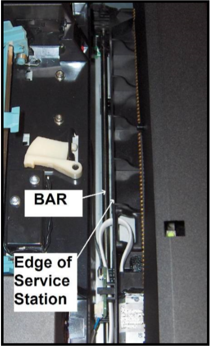
| 10. Look down through open area, in the Print Engine, to make sure the Service Station is aligned with the “Bar”; (Service Station Drive Shaft) as shown. If the Printhead Cartridge is not installed (has been removed), you can look down through the top of the Print-Engine, through the Printhead Cartridge opening. If the Printhead Cartridge is still installed, you must open the Clamshell to see into this area; as shown. IMPORTANT! The Service Station must perfectly aligned with the “Bar” to prevent misalignment and jamming of the service station. |
||
| 11. GENTLY push in on the Service Station with one hand, while slowly turning the “Large Gear” clockwise with the other hand. It should be easy to turn this gear and the service station should start to drive into the print engine squarely. Once the Service Station moves about ¼ inch past the “Bar” (shown in previous step), stop turning the gear. Do NOT manually drive the Service Station into the print engine beyond this point. NOTE: The “Large Gear” is located on the non-operator side of Print Engine. You don’t need to open the Print Engine to access this gear. | ||
| 12. Turn the printer’s Main Power Switch ON; then press the control panel’s ON/OFF button. After printer initialization (~45 seconds) the Print Engine will automatically pull the Service Station the rest of the way in. NOTICE: If the Service Station should get jammed during this process (you hear motor stall noise or gear slipping noise); immediately turn OFF the printer’s Main Power Switch. This is one of the few exceptions for turning off the printer using the main power switch, before properly powering-down the print engine. Remove the Service station by turning the Large Gear counter-clockwise. Recheck that the Wiper Roller is properly installed and latched at each end. Then re-install the Service Station starting from step 8 above. Tip: The “Eject Service Station” button, located in “Service” drop-down menu in the M Series Toolbox, should be used if the service station needs to be removed in the future. | ||
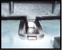
| 13. Verify that the wick, located on the bottom of the Service Station, is hanging into the waste ink trough; as shown (as viewed looking into the Service Station Slot, from the exit end of the printer). | ||
| 14. Carefully close and lock the Clamshell. | ||
| 15. Close the Ink Tank Door. NOTE: If using an older printer you will need to re-install the Exit Roller Cover plate, using the 4 screws, before closing the Ink Tank Door. Make sure the cover is installed in the proper orientation. TIP: Since the Exit Roller Cover is also an integral part of the frame structure; you may need to push in on the outer frames to get the screw holes in the Exit Roller Cover to align. |
||
| 16. Close the Top Cover | ||
| 17. Power the printer on and Test for proper operation. | ||